Testing Method For The Hydraulic Cylinders
1.Scope
This standard specifies the test method for hydraulic cylinders.
This standard applies to the type test and factory test of hydraulic cylinders (including double-acting hydraulic cylinders and single-acting hydraulic cylinders) with hydraulic oil (liquid) as working medium.
This standard does not apply to combined hydraulic cylinders.
2. Reference Standard
GB/T 786.1 Hydraulic and pneumatic graphic symbol
GB 2349 Hydraulic and pneumatic systems and components
Rod piston stroke series
3.Terms
3.1 Nominal pressure: Nominal value of hydraulic cylinder working pressure.
3.2 Minimum starting pressure: The lowest pressure at which the hydraulic cylinder is started.
3.3 Rodless cavity: Cavity without piston rod.
3.4 Rod cavity: Cavity with piston rod protruding.
3.5 Theoretical force: The force acting on the effective area of the piston or plunger; that is, the product of the oil pressure and the effective area of the piston or plunger.
3.6 Actual output: Thrust (or tension) output from the hydraulic cylinder.
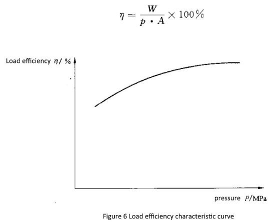
3.7 Load efficiency: The actual output of the hydraulic cylinder and the percentage of theoretical output.
3.8 Buffer: The process of decelerating the piston rod by throttling the oil at the end of the stroke of the hydraulic cylinder.
4.Symbols and units
The symbols used in this standard and their units are shown in Table 1.
Name | Symbol | Units | Units Name |
Pressure | p | MPa | Megapa |
Effective area of the piston rod | A | ㎡ | Square meter |
Actual output force | W | N | Newton |
Load efficiency | η | — | — |
5.Experimental setup and experimental conditions
5.1 experimental device
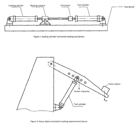
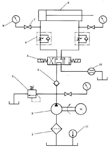
5.1.1 Hydraulic cylinder test device and the schematic diagram of the hydraulic system of the experimental device is shown in Figure 1~5.
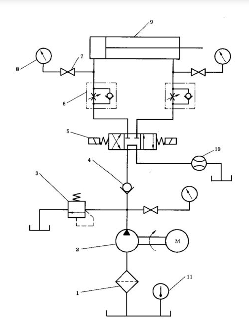

1-Filter
2-Hydraulic pump
3-Overflow valve
4-Check valve
5-Electromagnetic reversing valve
6-One-way throttle
7-Pressure gauge switch
8-Pressure gauge
9-Test cylinder
10-Flow meter
11-Thermometer
1-Filter
2-Hydraulic pump
3-Overflow valve
4-Check valve
5-Flow meter
6-Electromagnetic reversing valve
7-One-way throttle
8-Pressure gauge
9-Pressure gauge switch
10-Test cylinder
11-Loading cylinder
12-Stop valve
13-Thermometer
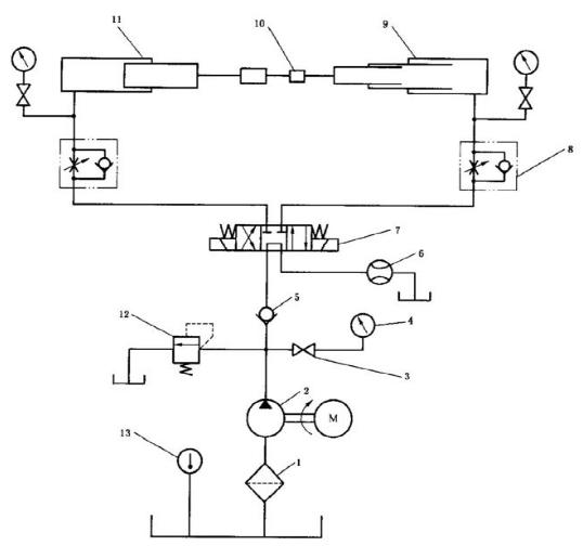

1-Filter
2-Hydraulic pump
3-Pressure gauge switch
4-Pressure gauge
5-Check valve
6-Flow meter
7-Electromagnetic reversing valve
8-One-way throttle
9-Test cylinder
10-Dynamometer
11-Loading cylinder
12-Overflow valve
13-Thermometer
5.1.2 Measurement accuracy
The measurement accuracy is measured in two stages, B and C. The allowable system error of the measurement system should meet the requirements of Table 2.
Table 2 measurement system allows system error
Controlled parameter | Allowable system error of the measurement system | ||
B级 | C级 | ||
Pressure | At less than 0.2Mpa gauge pressure/ kpa | ±3.0 | ±5.0 |
At a pressure equal to or greater than 0.2Mpa/ % | ±1.5 | ±2.5 | |
Temperature/ ℃ | ±1.0 | ±2.0 | |
Force/ % | ±1.0 | ±1.5 | |
Flow/ % | ±1.5 | ±2.5 | |
5.2 Experimental oil
5.2.1 Viscosity
The kinematic viscosity of the oil at 40 ° C should be 29mm2 / s ~ 74mm2 / s.
Note: except for special requirements
5.2.2 Temperature
Unless otherwise specified, the type test shall be carried out at 50 °C ± 2 °C, and the factory test shall be carried out at 50 °C ± 4 °C. The factory test allows the temperature to be lowered, in the range of 15 ° C ~ 45 ° C, but the test indicators should be adjusted according to temperature changes, to ensure that the product specifications can be achieved at 50 ° C ± 4 ° C.
5.2.3 Pollution degree rating
The solid particle contamination level of the test system oil shall not be higher than 19/16 specified in GB/T 14039.
5.3 stable conditions
In the test, the average display value of each controlled parameter is stable under the range specified in Table 3. The parameters should be measured and recorded under stable conditions.
Table 3 The averaged displayed valve of controlled parameter allows the range of variation
Controlled parameter | Average display valve allows variation range | ||
B级 | C级 | ||
Pressure | At less than 0.2Mpa gauge pressure/ kpa | ±3.0 | ±5.0 |
At a pressure equal to or greater than 0.2Mpa/ % | ±1.5 | ±2.5 | |
Temperature/ ℃ | ±2.0 | ±4.0 | |
Flow/ % | ±1.5 | ±2.5 | |
6. Experimental items and test methods
6.1 Test run
Adjust the pressure of the test system so that the hydraulic cylinder under test starts under no load conditions. And reciprocating the whole process several times, completely eliminating the air inside the hydraulic cylinder.
6.2 Starting pressure characteristic test
After the test run, adjust the relief valve under no-load conditions, so that the pressure of the rodless chamber (double piston rod cylinder, both chambers) is gradually increased. When the hydraulic cylinder is started, the starting pressure is recorded as Minimum starting pressure.
6.3 Pressure test
The piston parts of the hydraulic cylinders under test should be stopped at the two ends of the stroke (the single-acting hydraulic cylinder should reach at the stroke limit position), and 1.5 times working pressure should be applied to the working chamber, the type test should be kept for 2 minutes.
Special requirements are separately specified
6.4 Durability test
Under the rated pressure, the hydraulic cylinder under test is continuously operated at the highest speed required by the design, and the speed error is ±10%. Continuous operation for more than 8 hours at a time, during the test, the parts of the hydraulic cylinder to be tested shall not be adjusted. Record the cumulative travel.
6.5 Leak test
6.5.1 Internal leakage
The working chamber of the hydraulic cylinder to be tested is put into oil, pressurized to a rated pressure or a user-specified pressure, and the amount of leakage through the piston to the unpressurized chamber is measured.
6.5.2 External leakage
When performing the tests specified in 6.2, 6.3, 6.4, and 6.5.1, check the leakage of the piston rod seal; check for leaks at each static seal, joint surface and adjustable mechanism of the cylinder.
6.6 Buffer test
The buffer valve of the working chamber of the tested hydraulic cylinder is completely loosened, the test pressure is adjusted to 50% of the nominal pressure, and run the hydraulic cylinder with the maximum designed speed to detect the buffering effect when running until the buffer valve is fully closed.
6.7 Load efficiency test
Install the dynamometer on the piston rod of the hydraulic cylinder under test, keep the hydraulic cylinder under test running at a constant speed, calculate the load efficiency under different pressure according to the following formula, and draw the load efficiency characteristic curve, as shown in Figure 6
6.8 High temperature test
At rated pressure, the working fluid of 90 °C should be input to the hydraulic cylinder under test, and the full stroke was reciprocated for 1 h.
6.9 Itinerary inspection
The piston and the plunger of the hydraulic cylinder to be tested were stopped at the extreme positions of both ends of the stroke, and the stroke length should be measured.
7. Type test
Type testing should include the following items:
– commissioning (refer to 6.1);
– starting pressure characteristic test (refer to 6.2);
– withstand voltage test (refer to 6.3);
– durability test (refer to6.4);
– leak test (refer to 6.5);
– buffer test (refer to 6.6);
– load efficiency test (refer to 6.7);
– high temperature test (when required for the product)) (refer to 6.8);
– itinerary inspection (refer to 6.9)
8. Factory test
The factory test should include the following items:
– commissioning (Ref. 6.1);
– start pressure characteristic test (refer to 6.2);
– withstand voltage test (Ref. 6.3);
– leak test (refer to 6.5);
– durability test (refer to6.4);
– the itinerary test (refer to 6.9);


